Thank you to everybody for your assistance. I managed to get to where I wanted thanks to instructions provided by @dual_sport_dork
Thank you, thank you, thank you!
Not sure if anyone can help me here. I am pretty lost and confused and wouldn’t mind if someone could ELI5 something for me.
I’ve never used a real CAD software before yesterday night and I’m struggling a bit, I tried googling things but it’s just sending me deeper into a rabbit hole of things I do not understand yet.
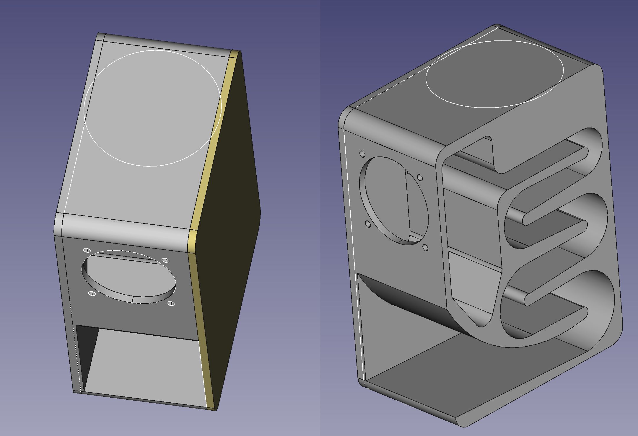
I’m trying to make this speaker enclosure I’ve seen just to do something with this shitty bluetooth speaker I have, so I decided to recreate the enclosure myself.
Long story short, I realized I kinda screwed myself after disassembling the bluetooth speaker and now I need to make a 2mm deep pocket on top of the case to snap in the buttons module. I don’t really feel like starting the design again from scratch.
Anyway, as you can see in the attached image, I need to make a big round pocket on top, but both side panels are separate bodies so my pocket only goes through the main body and ignores the 2 other bodies.
I can think of other ways to achieve what I want but I’d really like to figure out a way to do it from where I am right now, if possible. I’ve seen the term shape binder and “union” in my searches but I can’t quite figure it out.
Thank you to anyone who bothered reading this lol
EDIT:
For anyone who might see this and is curious about how the enclosure is performing, I finished printing the main body and assembled it to test. Am still missing the side panels and I have to design some kind of flange cover for the driver but here’s what I got so far:
I’m not sure which car you have. I’m still a student so I get AutoCAD as part of my tuition. I believe in AutoCAD you can make cuts in the assembly. Another option might be to save the assembly as one part which I think you can do and edit it from there but then you can’t go back to editing each part.
Hmm well I could try something like that as long as I can still export each part as individual STL files. I could just make that my last step. I’ll look into that, thank you!
Unfortunately I don’t have AutoCAD but I do have friends that have it. As a last resort I can always send them my file and have them do that last step for me.
Unfortunately if you want to keep the pieces separate, the best bet might be to sketch it in the assembly and measure the relevant parts in the assebly to change the cuts in each piece.
You are not logged in. However you can subscribe from another Fediverse account, for example Lemmy or Mastodon. To do this, paste the following into the search field of your instance: !3dprinting@lemmy.world
3DPrinting is a place where makers of all skill levels and walks of life can learn about and discuss 3D printing and development of 3D printed parts and devices.
The r/functionalprint community is now located at:
!functionalprint@kbin.social
or !functionalprint@fedia.io
There are CAD communities available at:
!cad@lemmy.world or !freecad@lemmy.ml
Rules
No bigotry - including racism, sexism, ableism, homophobia, transphobia, or xenophobia. Code of Conduct.
Be respectful, especially when disagreeing. Everyone should feel welcome here.
No porn (NSFW prints are acceptable but must be marked NSFW)
No Ads / Spamming / Guerrilla Marketing
Do not create links to reddit
If you see an issue please flag it
No guns
No injury gore posts
If you need an easy way to host pictures, https://catbox.moe may be an option. Be ethical about what you post and donate if you are able or use this a lot. It is just an individual hosting content, not a company. The image embedding syntax for Lemmy is 


I’m not sure which car you have. I’m still a student so I get AutoCAD as part of my tuition. I believe in AutoCAD you can make cuts in the assembly. Another option might be to save the assembly as one part which I think you can do and edit it from there but then you can’t go back to editing each part.
Hmm well I could try something like that as long as I can still export each part as individual STL files. I could just make that my last step. I’ll look into that, thank you!
Unfortunately I don’t have AutoCAD but I do have friends that have it. As a last resort I can always send them my file and have them do that last step for me.
Unfortunately if you want to keep the pieces separate, the best bet might be to sketch it in the assembly and measure the relevant parts in the assebly to change the cuts in each piece.